Sunday, December 1, 2013

lcd code for Beginners

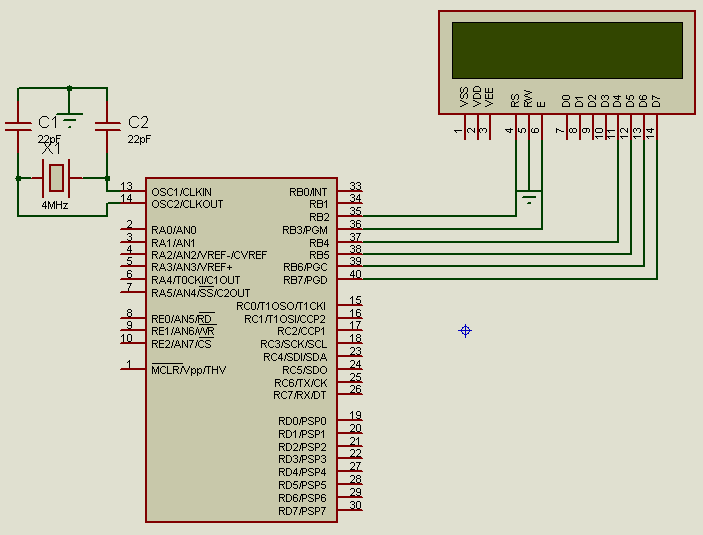
Higher nibble of PORTB connected to Higher nibble of LCD DATA


*********************************************************************************
code here
*********************************************************************************
/*compiler-hitech c
   frequency-4MHz */
#include "pic.h"
#define _XTAL_FREQ 4e6
#define LCD_RS RB2
#define LCD_RW RB1
#define LCD_EN RB3
#define LCD_DATA PORTB
#define LCD_STROBE() ((LCD_EN = 1),(LCD_EN=0))

void
lcd_write(unsigned char c)
{
__delay_us(40);

  LCD_DATA &= 0x0F;    

 LCD_DATA|=( c & 0xF0 );

  LCD_STROBE();
 
 LCD_DATA &= 0x0F;
   

  LCD_DATA|= ( ( c<<4 ) & 0xF0 );
//  
  LCD_STROBE();
}

/*
 * Clear and home the LCD
 */

void
lcd_clear(void)
{
LCD_RS = 0;
lcd_write(0x1);
__delay_ms(2);
}

/* write a string of chars to the LCD */

void
lcd_puts(const char * s)
{
LCD_RS = 1; // write characters
while(*s)
lcd_write(*s++);
}

/* write one character to the LCD */

void
lcd_putch(char c)
{
LCD_RS = 1; // write characters
lcd_write( c );
}


/*
 * Go to the specified position
 */

void
lcd_goto(unsigned char pos)
{
LCD_RS = 0;
lcd_write(0x80+pos);
}

/* initialise the LCD - put into 4 bit mode */
void
lcd_init()
{
char init_value;


init_value = 0x30;

TRISB=0;
LCD_RS = 0;
LCD_EN = 0;
LCD_RW = 0;

__delay_ms(15); // wait 15mSec after power applied,
LCD_DATA = init_value;

LCD_STROBE();
__delay_ms(5);
LCD_STROBE();
__delay_us(200);
LCD_STROBE();
__delay_us(200);
LCD_DATA = 0x20; // Four bit mode

LCD_STROBE();

lcd_write(0x28); // Set interface length
lcd_write(0xC); // Display On, Cursor On, Cursor Blink
lcd_clear(); // Clear screen
lcd_write(0x6); // Set entry Mode
}

void main(){
lcd_init();
lcd_goto(0);
lcd_puts("1.it works");
for(;;)continue;
}
*********************************************************************************
hex here.
*********************************************************************************
:100000000A128A11692F00308A000408840A8207C4
:10001000003431342E3469347434203477346F34FE
:0800200072346B3473340034B8
:100ED20083010A128A116D2F0A128A119B270A12A4
:100EE2008A1100300A128A117F270A128A110130F0
:100EF2000A128A1183270A128A117E2FF200061122
:100F0200803ED92FF2000615720884000A128A1157
:100F120003200A128A11003803190800720884009B
:100F22000A128A1103200A128A11D9270A128A1177
:100F3200F20A852F83168601831214300611861158
:100F42008610F5007930F400F40BA52FF50BA52FD0
:100F5200AA2F3030FD278600073086158611F5004E
:100F62007D30F400F40BB32FF50BB32FFD27423085
:100F720086158611F400F40BBC2F6400FD27423065
:100F820086158611F400F40BC42F64002030FD276F
:100F92008600283086158611D9270A128A110C304C
:100FA200D9270A128A11EE270A128A110630D92F7E
:100FB200F1000D30F000F00BDC2F0F30FD2786051D
:100FC2007108F03986040F30861586118605710E78
:100FD200F039860486158611080001300611D927DA
:100FE2000A128A110330F3009730F200F20BF72F46
:0E0FF200F30BF72FFC2F0800831203130800E7
:00000001FF
*********************************************************************************


For any pin of pic to higher nibble of LCD DATA


*********************************************************************************
code here
*********************************************************************************
/*compiler-hitech c
   frequency-4MHz */


#include "pic.h"
#define _XTAL_FREQ 4e6


#define LCD_RS RB2
#define LCD_RW RB1
#define LCD_EN RB3

#define LCD_D7 RB4   /*choose any pin here (example RD3,RC8............)
#define LCD_D6 RB5
#define LCD_D5 RB6
#define LCD_D4 RB7   */


#define LCD_STROBE() ((LCD_EN = 1),(LCD_EN=0))

/* write a byte to the LCD in 4 bit mode */
 char LCD_DATA;
void data_split(char nibble);
void
lcd_write(unsigned char c)
{
__delay_us(40);
data_split( LCD_DATA &= 0x0F);    
data_split(LCD_DATA|=( c & 0xF0 ));

  LCD_STROBE();
 
data_split(LCD_DATA &= 0x0F);
   

data_split( LCD_DATA|= ( ( c<<4 ) & 0xF0 ));
//  
  LCD_STROBE();
}

/*
 * Clear and home the LCD
 */

void
lcd_clear(void)
{
LCD_RS = 0;
lcd_write(0x1);
__delay_ms(2);
}

/* write a string of chars to the LCD */

void
lcd_puts(const char * s)
{
LCD_RS = 1; // write characters
while(*s)
lcd_write(*s++);
}

/* write one character to the LCD */

void
lcd_putch(char c)
{
LCD_RS = 1; // write characters
lcd_write( c );
}


/*
 * Go to the specified position
 */

void
lcd_goto(unsigned char pos)
{
LCD_RS = 0;
lcd_write(0x80+pos);
}
/* initialise the LCD - put into 4 bit mode */
void
lcd_init()
{
char init_value;


init_value = 0x30;

TRISB=0;  //initialize the pins used for lcd to output
LCD_RS = 0;
LCD_EN = 0;
LCD_RW = 0;
__delay_ms(15); // wait 15mSec after power applied,
LCD_DATA = init_value;
data_split(LCD_DATA);
LCD_STROBE();
__delay_ms(5);
LCD_STROBE();
__delay_us(200);
LCD_STROBE();
__delay_us(200);
LCD_DATA = 0x20; // Four bit mode
data_split(LCD_DATA);
LCD_STROBE();

lcd_write(0x28); // Set interface length
lcd_write(0xC); // Display On, Cursor On, Cursor Blink
lcd_clear(); // Clear screen
lcd_write(0x6); // Set entry Mode
}
 void data_split( char nibble ) {

    LCD_D7= (unsigned int)((nibble & 128)>>7);
    LCD_D6 =(unsigned int)((nibble & 64)>>6);
    LCD_D5 =(unsigned int)((nibble & 32)>>5);
    LCD_D4 =(unsigned int)((nibble & 16)>>4);
}
void main(){
lcd_init();
lcd_goto(0);
lcd_puts("2-it works");
for(;;)continue;
}


*********************************************************************************
hex here.
*********************************************************************************
:100000000A128A11182F00308A000408840A820715
:10001000003432342D3469347434203477346F34FE
:0800200072346B3473340034B8
:100E3000F90183010A128A111D2F0A128A114B2708
:100E40000A128A1100300A128A112F270A128A11F7
:100E500001300A128A1133270A128A112E2FF40048
:100E60000611803E8F2FF4000615740884000A12C4
:100E70008A1103200A128A11003803190800740825
:100E800084000A128A1103200A128A118F270A127B
:100E90008A11F40A352F8316860183121430061145
:100EA00086118610F7007930F600F60B552FF70BF8
:100EB000552F5A2F3030F9007908B1270A128A11BC
:100EC000073086158611F7007D30F600F60B662F89
:100ED000F70B662FFD27423086158611F600F60BBC
:100EE0006F2F6400FD27423086158611F600F60B41
:100EF000772F64002030F9007908B1270A128A118F
:100F00002830861586118F270A128A110C308F27F8
:100F10000A128A11EE270A128A1106308F2FF30067
:100F20000D30F200F20B922F0F30F9057908B1273E
:100F30000A128A117308F039F9047908B1270A12E4
:100F40008A110F3086158611F9057908B1270A1222
:100F50008A11730EF039F9047908B12786158611C4
:100F60000800F100F00007300310F00CFF3E031DF5
:100F7000B42F701CBE2FFD270616C02FFD270612AA
:100F80007108F00006300310F00CFF3E031DC32F64
:100F9000701CCD2FFD278616CF2FFD2786127108D6
:100FA000F00005300310F00CFF3E031DD22F701C23
:100FB000DC2FFD270617DE2FFD2706137108F00032
:100FC00004300310F00CFF3E031DE12F701CEB2FCB
:100FD000FD2786170800FD2786130800013006113B
:100FE0008F270A128A110330F5009730F400F40BB2
:100FF000F72FF50BF72FFC2F0800831203130800BF
:00000001FF
*********************************************************************************


Friday, November 15, 2013

control fan by tv remote


While watching TV I feel warm, i need to turn on fan but “I am lazy”, then I think why couldn’t use the same Sony TV remote controller to control fan and bulb
There are two problems I need to decode the Sony remote controller and adjust the fan input. I had learned about firing angle control of TRIAC so that part is not a difficult.

                                  Basically, the zero crossing detector circuit interrupt the microcontroller after every 10ms,this interrupt command microcontroller to generate firing pulses, firing pulses are delayed with respect to this interrupt in the range of 1ms to 9ms, figure(2) below shows  out puts for different firing angles. In order to control both positive and negative cycles the frequency of firing pulses should be 100 Hz(means should produce two pulses per 50Hz ,one for positive cycle and another for negative cycle).


Circuit description

The complete circuit can be divided into
SIRC-remote decoding
Zero crossing detection
TRIAC controller

SIRC-remote decoding

I goggled  about “remote controller”   I got many types, each manufacture use different set of protocols for example RC80 is used by Panasonic RC5 is used by Philips and SIRC is used by Sony fortunately which is the simplest to decode
In order to eliminate ambient light sources from interfering with the data stream transmitted modulated light is used, this modulation is centred around different frequencies depending on manufacture and varies from 32khz to 56khz in the case of Sony the modulation centre is 40khz which means we need a IR receiver that can receive the modulation infra red light and convert it to TTL signal for a PIC. There are a number of IR receiver available, each having a specific centre frequencies, here i use TSOP 1738 which has a centre frequency of 38 kHz. The figure below shows the internal block diagram of TSOP 1738


Output-Rout  is normally high as you can see from block diagram it has a pull-up resister that keep logic high when no signal present when infra-red signal is detected output is low(active low output).
SONY protocol, SIRC (serial infra red control) is an infra red light remote control communication that uses a form of pulse width modulation (PWM) to build serial interface. The most common protocol is 12-bit interface. Figure below shows a series of pulses build up 12-bit packet


The header bit is 2.4ms in length, logic 1 is 1.8ms (1.2ms high+0.6ms low), logic 0 is 1.2ms (0.6ms high +0.6ms low). The packet consist of start bit command code(7 bit) which present the actual button pressed on the remote control, and device code (5 bit) which present  a TV,VCR,CD player and etc. That signal is inverted to Rout of TSOP 1738 when the data is sent 45ms delay timed before the next packet is sent and it is repeated for as long as the key is pressed. Table shown below is some list of key command code for TV (device code=1)

Zero crossing detector

Figure below shows the circuit diagram of the zero crossing detector, the LED side of opto- coupler is connected to the phase through 200k(.25w),a 10k is connected in between ground and emitter.


                The working of the circuit is simple, whenever a positive cycle comes, the LED emits and transistor turn on, hence a 5V appears in between emitter and ground, there is no role for a negative voltage (means diode is in reverse bias) , so the output will be a 50Hz square wave of approximate turn on 10ms, since I use an opto- coupler for high volt zero crossing the chance of high volt risk is eliminated.

TRIAC controller

Moc3021 is an opto- coupler TRIAC driver
Since the load is an inductive load (single phase induction motor) a snubber should be added in order to avoid the risk of dv/dt rise here i use .1uf and 2k4.


*********************************************************************************

 CODE here

********************************************************************************

/*compiler-hitech c

   frequency-4MHz */

#include "pic.h"
#define _XTAL_FREQ 4e6
__CONFIG(0x005A);

unsigned counter = 0;
unsigned input_data, bit_count;
 unsigned int i=237;
enum {
        Idle,
        Start_bit,
        Capture_bit
};

char Current_state = Idle;
char got_data = 0;
char Command_code, Device_code;
void pulse(void){
RC4=1;
__delay_us(100);
RC4=0;
}
void interrupt ISR(){
 if(INTF){
        switch (Current_state){
           case Idle:
                      INTEDG = 1;        //interrupt on rising edge.
                      counter = 0;
                      Current_state = Start_bit;
                      break;
           //found the rising edge, check lenght for 2.4ms
           case Start_bit:
                      //correct signal, move on to next state
                      if(counter == 4) {
                         counter = 0;
                         bit_count = 0;
                         input_data = 0;
                         Current_state = Capture_bit;
                         } else {
                            //fault signal, reset to Idle
                            Current_state = Idle;
                         }
                      break;
           case Capture_bit:
                      //check plus length for 0 or 1
                      if(counter == 2){
                         input_data >>= 1;         // add 0 to received data
                         bit_count++;
                      }else {
                         if(counter == 3){
                            input_data >>= 1;
                            input_data |= 0x8000;     //add 1 to received data
                            bit_count++;
                         } else {
                            //error occurs, reset to Idle state
                            INTEDG = 0;    //interrupt on falling edge.
                            Current_state = Idle;
                         }
                       }
                      //compleat 12 bit
                      if(bit_count >= 12){
                         got_data = 1;
                         input_data >>= 4;
                         INTEDG = 0;      //interrupt on falling edge.
                         Current_state = Idle;
                      }
                      counter = 0;
                      break;
            default: Current_state = Idle;
        }
     INTF = 0;       //clear interrupt flag.
}

 }

                    }

//******************************************************************************
// MAIN  MAIN  MAIN MAIN
//******************************************************************************
void main() {


     INTE = 1;          //enable RB0 interrupt.
     INTEDG = 0;        //interrupt on falling edge.

     ADCON1 = 0x0F;              //all digital I/O
//******************************************************************************
// Timer2 interrupt set up, interrupt every 600us
//******************************************************************************
PR2 = 149;                  //preload timer2 comparator value.
T2CON = 1;                  //timer off, prescaler 1:16
TMR2 = 0;                   //reset value timer2
TMR2IF = 0;            //clear interrupt flag.
TMR2IE = 1;            //enable timer2 interrupt.
TMR2ON = 1;           //timer2 is on
TMR0IE=1;                //enable timer0 interrupt.
TMR0IF=0;                 //clear interrupt flag.
T0CS=1;                    //Transition on RA4/T0CKI pin
PSA=0;                    // Prescaler is assigned to the Timer0 module

PS2=1;
PS1=0;
PS0=1;                    //1:64 timer0 prescalar rate


TMR1IE=1;                //enable timer2 interrupt.
TMR1IF=0;                //clear interrupt flag.
TMR1ON=1;                //turn on timer1

T1CKPS1=0;                //timer1- 1:2 prescale value
T1CKPS0=1;

CCP1IE=1;//ccp1 interrupt is enabled
CCP1IF=0;//clear interrupt flag
TRISC2=1;//RC2 input
TRISC4=0;//RC4 output

CCP1M3=0;//ccp1 interrupt on every rising edge
CCP1M2=1;
CCP1M1=0;
CCP1M0=1;
//******************************************************************************
// Global interrupt enable
//******************************************************************************
     PEIE=1;                    //peripheral interrupt enable bit
     GIE = 1;             //enable global interrupt


     TRISB0=1;//RB0 input
     while(1){
if(i<=240){//disable underflow
i=240;
RC4=0;
}
if(i>=255){//disable over flow
i=255;

}
          if(got_data){
            Command_code = input_data & 0x7F;
            Device_code = input_data >> 7;
            got_data = 0;
            if(Device_code == 1){

if(Command_code==18){//vol '+' for increase speed
i++;
Command_code=0;

}
if(Command_code==19){//vol '-' for decrease speed

i--;

Command_code=0;
}
if(Command_code==0X10){//channel '+' for turn on

TRISC4=0;


}
if(Command_code==0X11){ //channel '-'for turn off

TRISC4=1;


}

               TMR2IE = 0;            //disable timer2 interrupt.
               __delay_ms(100);
               TMR2 = 0;                   //reset value timer2
               TMR2IE = 1;            //enable timer2 interrupt.
            }
          }
     }

}

*********************************************************************************

HEX here

*********************************************************************************

:100000000C28102818282828FE00030ECB0004080E
:10001000CC000A08CD000D2827298B185528612807
:10002000831603130117C201C301C701C70A602861
:100030004208043A4304031D26280230C201C301CA
:10004000C001C101C401C501C7006028C701602803
:100050004208023A4304031D31280310C50CC40CA6
:100060003A284208033A4304031D3E280310C50CF6
:1000D00000304302063003194202031C7428C70192
:1000E000C201C3018316011383128C100C1D7E28DC
:1000F000FF300C118E0050088F0010140C1C892842
:100100000C10101036218F018E016730810083168C
:1001100081120B1D91280B11831281018316811608
:1001200036214D088A004C0884004B0E8300FE0ED9
:100130007E0E0900831603130113C70108000F3058
:100140000B16831601139F00953092000130831225
:10015000920091018C1083168C14831212158B1649
:100160000B118316811681110115811001140C14D5
:1001700083120C1010149012101683160C15831293
:100180000C11831607150712831297111715971074
:1001900017140B178B178316061400305102F13019
:1001A000031950020318D928F030D000D10183126E
:1001B000071200305102FF3003195002031CE328DC
:1001C000FF30D000D10149080319CD284408C600EA
:1001D000C6134508CF004408CE0007300310CF0CEB
:1001E000CE0CFF3E031DEE284E08C800C901480B87
:1001F000CD284608123A031D0129D00A0319D10A55
:10020000C6014608133A031D0C290130D002003004
:10021000031CD103D102C6014608103A8316031904
:1002200007124608113A83160319071682308316FF
:100230008C10CF00DD30CE00CE0B1C29CF0B1C293B
:10024000212983120313910183168C14CD28ED30DC
:10025000C001C101C201C301C401C501C601C7017A
:10026000C801C901D000D10183019F282130831228
:100270000716CA00CA0B3A29831203130712080093
:02400E005A0056
:00000001FF

*******************************************************************************